
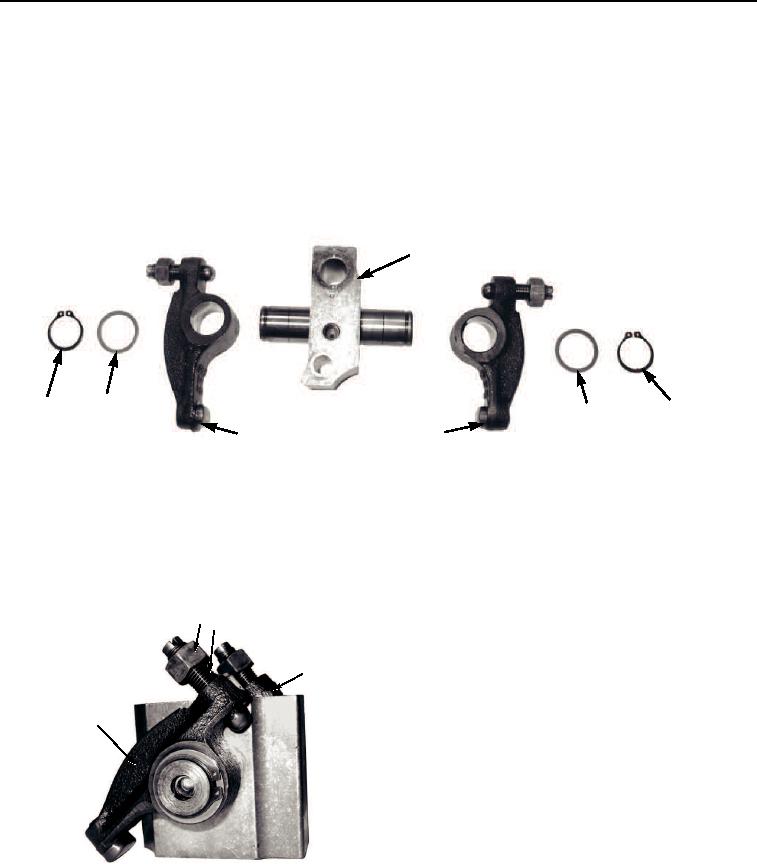
2
3
1
4
TM 5-3810-305-23
0031
DISASSEMBLY
NOTE
The following is a maintenance instruction for one rocker shaft support assembly.
Maintenance instruction for remaining three rocker shaft support assemblies is identical.
Before disassembly of rocker shaft support assemblies, mark on each side of rocker shaft
support and rocker levers (I) or (E) for intake or exhaust to aid in assembly.
1.
Remove two retaining rings (Figure 3, Item 1), thrust washers (Figure 3, Item 2) and intake and exhaust rocker
levers (Figure 3, Item 3) from rocker shaft support assemblies (Figure 3, Item 4).
M0024105
Figure 3. Rocker Lever and Push Rods Disassembly.
NOTE
DO NOT disassemble rocker shaft support. They are serviced as an assembly.
2.
If inspection shows adjusting nuts (Figure 4, Item 1) and rocker adjusting screws (Figure 4, Item 2) are
defective, remove and discard from intake and exhaust rocker levers (Figure 4, Item 3).
1 2
3
3
M0025105
Figure 4. Rocker Lever and Push Rods Disassembly.
END OF TASK
03/15/2011Rel(1.8)root(maintwp)wpno(M00036)