TM 5-3810-305-23
0066
REMOVAL - Continued
Dash Panel
1.
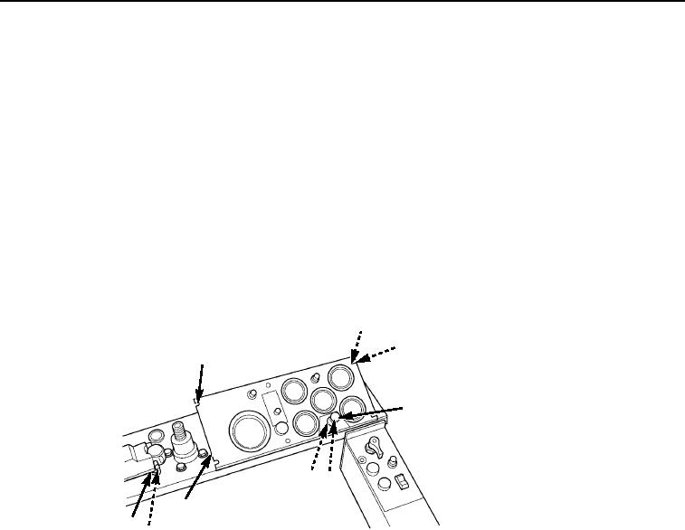
Remove six bolts (Figure 1, Item 1), six lockwashers (Figure 1, Item 2) and washers (Figure 1, Item 3) from
dash panel (Figure 1, Item 7). Discard lockwashers.
2.
Loosen jam nut (Figure 1, Item 5) and remove cold start knob (Figure 1, Item 4) from dash panel
(Figure 1, Item 7).
3.
Remove jam nut (Figure 1, Item 5) and cable locknut (Figure 1, Item 6). Pull cold start cable out of dash panel
(Figure 1, Item 7). Discard locknut.
4.
Disconnect two plastic cannon-style electrical connectors under right-hand corner of dash panel
(Figure 1, Item 7).
5.
Remove screw (Figure 1, Item 9) from turn signal switch mounting band to release ground wire and clamp
(Figure 1, Item 8), and remove dash panel (Figure 1, Item 7) assembly to a work bench for further disassembly.
2
3
1,2,3
4
6 5
7
9
8
M0500105
Figure 1. Dash Panel Removal.
NOTE
Tag wires to aid installation.
6.
Disconnect wires (Figure 2, Item 9) from back of gage and light.
7.
Remove two nuts (Figure 2, Item 15), washers (Figure 2, Item 14), and bracket (Figure 2, Item 13) from dash
panel (Figure 2, Item 1).
8.
Pull gage (Figure 2, Item 8) out of dash panel (Figure 2, Item 1).
9.
Remove light bulb assembly (Figure 2, Item 12) from gage (Figure 2, Item 8).
10.
Remove filter (Figure 2, Item 11) from light bulb (Figure 2, Item 12).
11.
Push down and twist light bulb (Figure 2, Item 12) to remove from socket (Figure 2, Item 10).
12.
If necessary, use same procedure to remove remaining five gages.
13.
Disconnect two wires (Figure 2, Item 7) and remove nut (Figure 2, Item 2) and internal tooth washer
(Figure 2, Item 3) from dash panel (Figure 2, Item 1).
14.
Pull light socket (Figure 2, Item 6) through dash panel (Figure 2, Item 1).
03/15/2011Rel(1.8)root(maintwp)wpno(M00072)

