TM 5-3810-305-23
0074
INSTALLATION
1.
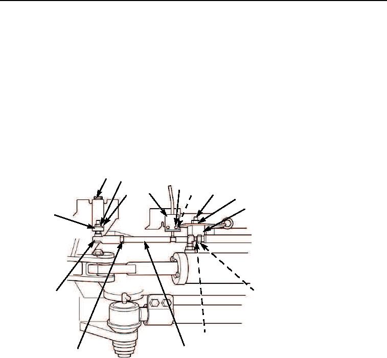
Install plate (Figure 3, Item 4) and two capscrews (Figure 3, Item 2) on vehicle.
2.
Install jam nut (Figure 3, Item 15) on rod (Figure 3, Item 14).
3.
Install rod (Figure 3, Item 14) into rod end (Figure 3, Item 16).
4.
Install rod (Figure 3, Item 14) into the large diameter hole side of block (Figure 3, Item 11).
5.
Install block (Figure 3, Item 11) with rod (Figure 3, Item 14), two washers (Figure 3, Item 12), capscrews
(Figure 3, Item 13), washers (Figure 3, Item 10), and new locknuts (Figure 3, Item 9) on vehicle.
6.
Install rod end (Figure 3, Item 16), washer (Figure 3, Item 1) and jam nut (Figure 3, Item 3) on plate
(Figure 3, Item 4).
7.
Install switch (Figure 3, Item 5), two capscrews (Figure 3, Item 6), washers (Figure 3, Item 8) and locknuts
(Figure 3, Item 7) on vehicle.
2
3
6 7,8
5
9
4
10
11
1
12
16
13
14
15
M0153105
Figure 3.
Axle Centering Light Switch Assembly Installation.
03/15/2011Rel(1.8)root(maintwp)wpno(M00080)

