
TM 5-3810-305-23
0097
REMOVAL - Continued
WARNING
Weight of pivot and spindle assembly is approximately 69 lb (30 kg). Use adequate lifting
equipment to lift and support pivot and spindle assembly. DO NOT lift over personnel or let
personnel walk underneath suspended load. Failure to follow this warning may cause injury
or death to personnel.
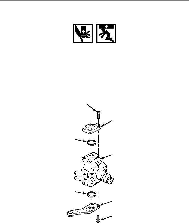
5.
Position hoist above pivot and spindle assembly (Figure 1, Item 3). Support pivot and spindle assembly
with sling.
6.
Remove eight bolts (Figure 1, Item 1), pivot cap (Figure 1, Item 2), and tie rod lever (Figure 1, Item 4) from
spindle assembly (Figure 1, Item 3).
7.
Remove and measure shim packs (Figure 1, Item 5) from spindle assembly (Figure 1, Item 3).
Record measurements and locations of shims.
1
2
5
3
5
4
1
M0303105
Figure 1.
Pivot and Spindle Assembly Removal.
03/15/2011Rel(1.8)root(maintwp)wpno(M00107)