
2
1
TM 5-3810-305-23
0096
INSTALLATION - Continued
M0312105
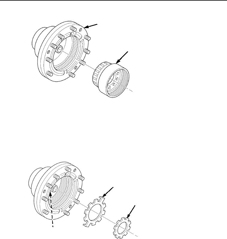
Figure 9. Planetary Wheel End Installation.
4.
Install centering cone (Figure 10, Item 3), new lockwasher (Figure 10, Item 1), and spindle nut
(Figure 10, Item 2). Tighten spindle nut according to procedures in Steps a, b, and c below:
a.
Tighten spindle nut (Figure 10, Item 2) while rotating hub to correctly position all components
(bearings and spindle cone). Tighten spindle nut to 258 to 295 ft-lb (350 to 400 Nm).
b.
Apply 15.8 lb (70 N) tangential force to wheel stud. Adjust spindle nut (Figure 10, Item 2) by loosening
until rotation of hub is obtained.
c.
Secure spindle nut (Figure 10, Item 2) by bending tab on lockwasher (Figure 10, Item 1).
1
2
3
M0311105
Figure 10.
Planetary Wheel End Installation.
03/15/2011Rel(1.8)root(maintwp)wpno(M00106)