
TM 5-3810-305-23
0129
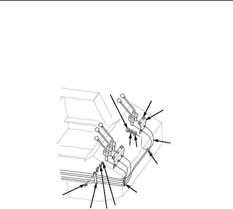
INSTALLATION - Continued
Valve Control Cables - Continued
5.
Install bracket (Figure 9, Item 5) with two capscrews (Figure 9, Item 4), new lockwashers (Figure 9, Item 3)
and nuts (Figure 9, Item 2).
6.
Tighten locking nuts (Figure 9, Item 2) and washers (Figure 9, Item 3) on bracket (Figure 9, Item 8).
7.
Position cable (Figure 9, Item 9) through clamps (Figure 9, Item 12) and install washer
(Figure 9, Items 8 and 9), and locknuts (Figure 9, Item 11).
8.
Position cable (Figure 9, Item 6) through clamps (Figure 9, Items 7 and 10) and install washers
(Figure 9, Items 8 and 9) and two new locknuts (Figure 9, Item 1).
1
2, 3, 4
5
6
9 8
7
10
8
11
12
9
M0560105
Figure 9. Valve Control Cables Installation.
03/15/2011Rel(1.8)root(maintwp)wpno(M00145)