
TM 5-3810-305-23
0138
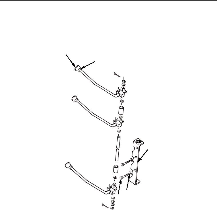
INSTALLATION
1.
Position bracket assembly (Figure 5, Item 3) under dash panel.
2.
Install two new lockwashers (Figure 5, Item 4) and two capscrews (Figure 5, Item 5).
3.
Install three jam nuts (Figure 5, Item 2) and knobs (Figure 5, Item 1) on handle and lock in place with jam nuts.
1
2
3
4
5
M2311105
Figure 5. Boom Hoist, Winch, and Outrigger Valve Controls Installation.
03/15/2011Rel(1.8)root(maintwp)wpno(M00154)