
TM 5-3810-305-23
0161
ASSEMBLY - Continued
NOTE
If any part(s) on worm gear axis have been replaced, shim thickness must be recalculated to
give 0 to 0.005 inch (0 to 0.13 mm) end play on worm gear.
14.
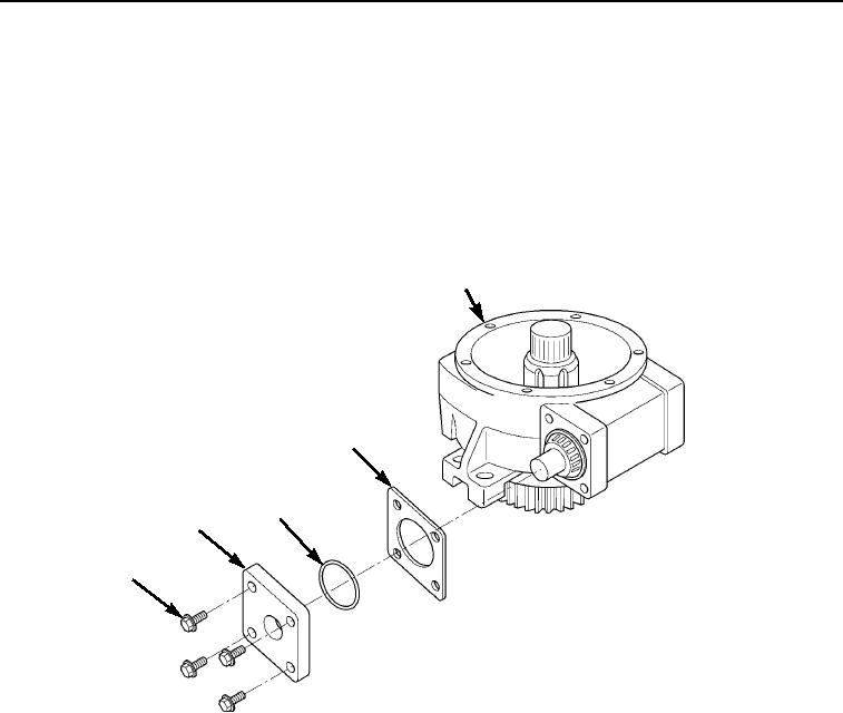
Install new o-ring (Figure 17, Item 3) and shim(s) (Figure 17, Item 4) on bearing retainer (Figure 17, Item 2).
15.
Install four capscrews (Figure 17, Item 1) and bearing retainer (Figure 17, Item 2) on housing
(Figure 17, Item 5). Tighten four capscrews to 58 ft-lb (79 Nm).
5
4
3
2
1
M0602105
Figure 17. Swing Gearbox Bearing Retainer Assembly.
03/15/2011Rel(1.8)root(maintwp)wpno(M00180)