
TM 5-3810-305-23
0161
INSTALLATION
1.
Using adequate hoist and sling, support swing gearbox (Figure 21, Item 1).
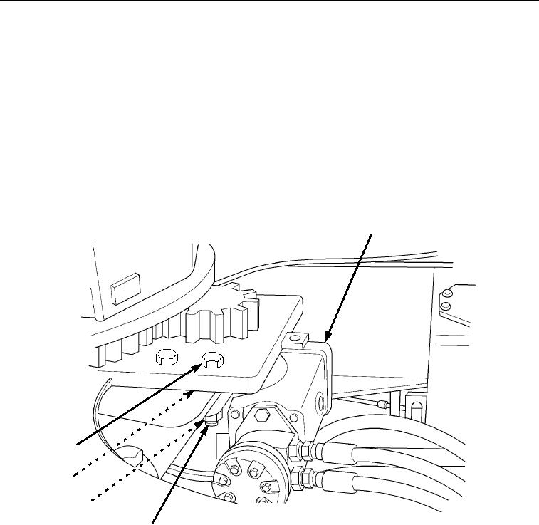
2.
Position swing gearbox (Figure 22, Item 1) in place.
NOTE
It will be necessary to rotate upperstructure by hand to access rear hardware.
3.
Attach a wrench to protruding shaft of swing box drive. Turn swing box drive clockwise to swing upperstructure
to the right and counterclockwise to swing to the left.
4.
Install four capscrews (Figure 22, Item 5), spacers (Figure 22, Item 4), washers (Figure 22, Item 3), and nuts
(Figure 22, Item 2). Tighten capscrews to 344 ft-lb (466 Nm).
1
5
4
3
2
M0598105
Figure 22. Swing Gearbox Installation.
END OF TASK
03/15/2011Rel(1.8)root(maintwp)wpno(M00180)