
TM 5-3810-305-23
0027
INSTALLATION - Continued
WARNING
Weight of the cylinder is approximately 80 lb (36 kg). Use adequate lifting equipment to lift
and support cylinder head. DO NOT lift over personnel or let personnel walk underneath
suspended load. Failure to follow this warning may result in injury or death to personnel.
2.
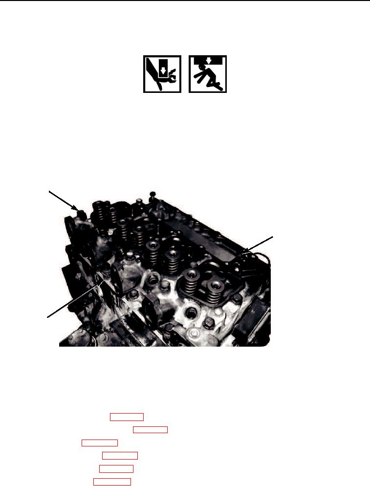
Using a suitable hoist and sling, install cylinder head (Figure 4, Item 2) carefully on block (Figure 4, Item 3),
making sure gasket stays in place.
3.
Lubricate and install 14 capscrews (Figure 4, Item 1) on cylinder head (Figure 4, Item 2). Tighten 14 capscrews
in sequence three separate times. First time, tighten capscrews to 29 ft-lb (39 Nm). Second time, tighten
capscrews to 62 ft-lb (84 Nm). Third time, tighten capscrews to 92 ft-lb (125 Nm).
1
2
3
M02101045
Figure 4.
Cylinder Head Installation.
END OF TASK
FOLLOW-ON MAINTENANCE
1.
Install manifold cover plate (WP 0041).
2.
Install rocker levers and push rods (WP 0031).
3.
Install valve covers (WP 0035).
4.
Install fuel injection tubes (WP 0049).
5.
Install exhaust manifold (WP 0042).
6.
Connect battery cables (WP 0076).
03/15/2011Rel(1.8)root(maintwp)wpno(M00032)