
TM 5-3810-305-23
FIELD MAINTENANCE
FUEL FILTER HEAD ASSEMBLY MAINTENANCE
INITIAL SETUP:
Materials/Parts (cont.)
Tools and Special Tools
Packing, Preformed (WP 0172, Table 1, Item 69)
Tool Kit, General Mechanic's (WP 0171, Table 1,
Item 17)
Qty: 1
Wrench, Oil Filter, Strap (WP 0171, Table 1, Item
Rag, Wiping (WP 0170, Table 1, Item 52) Qty: 1
32)
Wrench, Torque, Click, Ratcheting 3/8 Inch Drive,
References
75 ft-lb (WP 0171, Table 1, Item 36)
Materials/Parts
Equipment Condition
Lubricating Oil, Preservative and Break-In
Boom in horizontal position and fully retracted (TM
(WP 0170, Table 1, Item 45) Qty: 1
5-3810-305-10)
O-Ring (WP 0172, Table 1, Item 70) Qty: 1
Battery cables disconnected (WP 0076)
Fuel injection tubes disconnected (WP 0049)
REMOVAL
1.
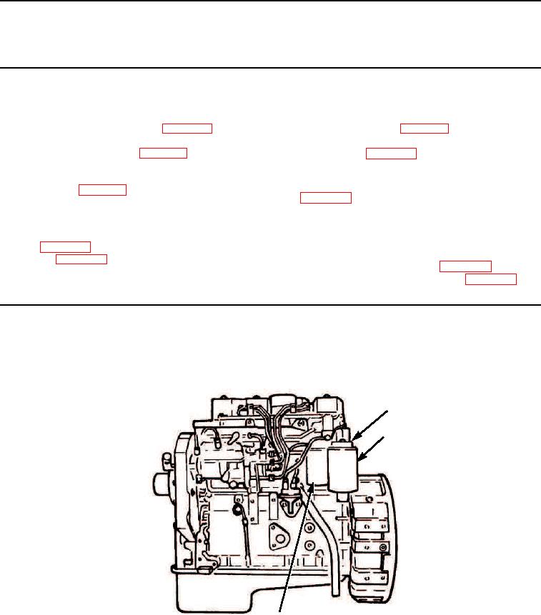
Remove secondary fuel filter (Figure 1, Item 3) and primary fuel filter (Figure 1, Item 2) from fuel filter head
(Figure 1, Item 1).
1
2
3
M0246105
Figure 1.
Fuel Filters and Head Assembly Removal.
03/15/2011Rel(1.8)root(maintwp)wpno(M00056)