TM 5-3810-306-20
f.
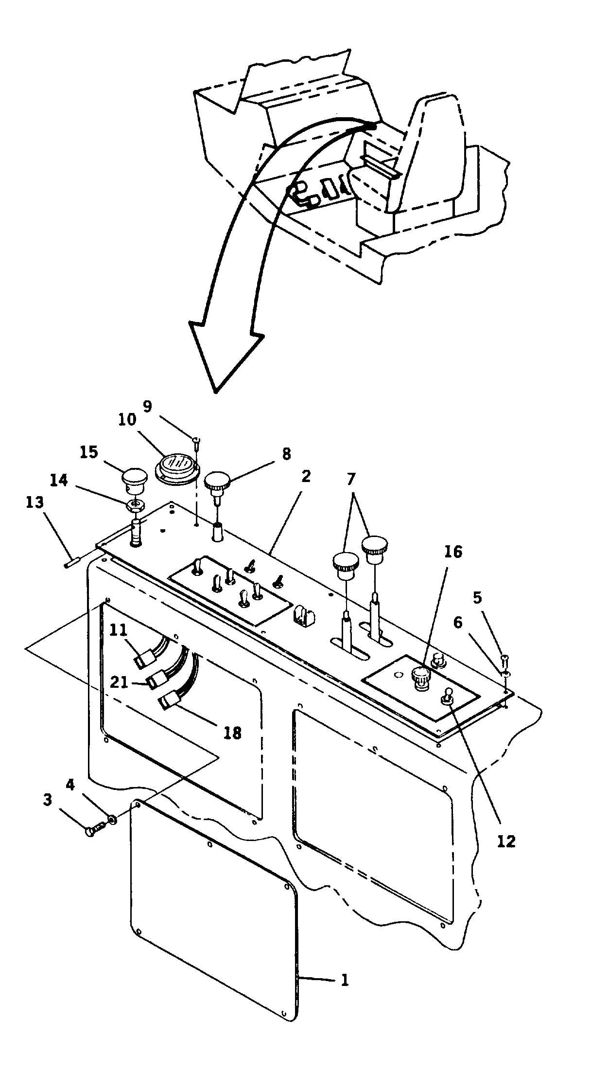
Remove control switch knob and nut (16).
g.
Remove fan high/low switch (12).
h.
Tag and disconnect two electrical connectors,
P3 (18), P6 (11) and wire no. 21 (21).
i.
Lift out side console panel (2).
3.
INSPECT PARTS FOR DAMAGE. REPLACE AS
REQUIRED.
INSTALLATION:
1.
INSTALL SIDE CONSOLE PANEL (2).
a.
Place panel over shifter arms.
b.
Install park brake control valve in panel and
secure with nut (14). Install and secure knob
(15) with roll pin (13).
c.
Install fan high/low switch (12).
d.
Install six screws (5) and grommets (6), to
secure console panel.
e.
Install swing brake knob (8) and two shifter
knobs (7).
f.
Position bubble level (10) and secure with three
screws (9).
g.
Connect electrical connectors, P3 and P6 and
wire no. 21.
h.
Connect heater temperature control switch (16).
2.
INSTALL ACCESS PANEL (1).
a.
Hold access panel (1) in place
b.
Align access panel (1) with side of cab console.
c.
Install five capscrews (3) and new lockwashers
($).
3.
INSTALL
OPERATOR’S
SEAT
AND
PEDESTAL. (REFER TO PAGE 15-27.)
4. CONNECT GROUND CABLE AT SHUNT. (REFER
TO PAGE 8-109.)
END OF TASK
8-22