TM 5-3810-306-20
Section I. HYDRAULIC CONTROL VALVE MAINTENANCE
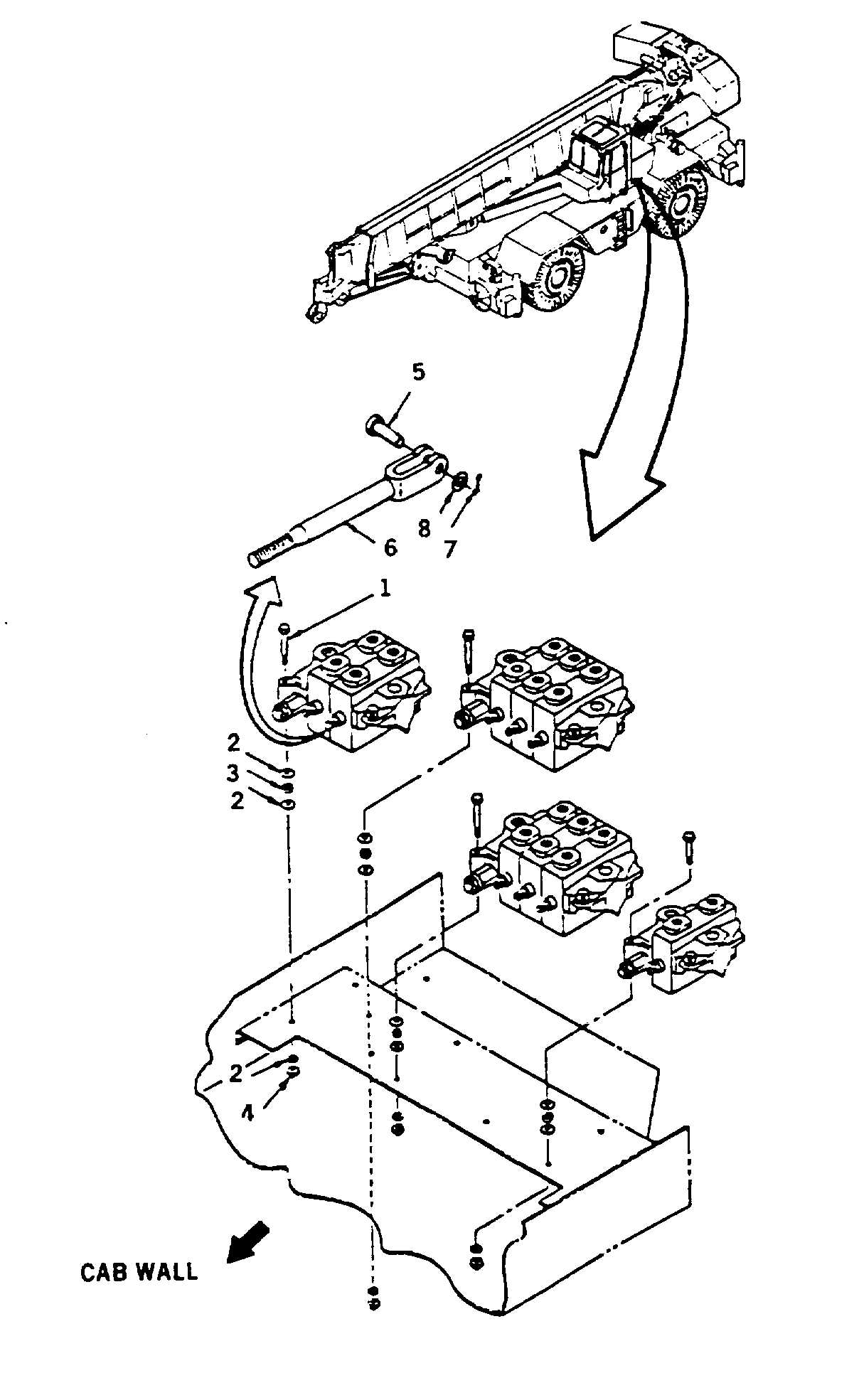
HYDRAULIC CONTROL VALVE INSTALLATION
TOOLS:
General mechanic’s tool kit: automotive (5180-00-177-7033)
SUPPLIES: Clean rags (Item 1, Appendix C)
Cotter pin (Item 37, Appendix C)
Loctite 545 (Item 13, Appendix C)
Hydraulic oil (Item 6, Appendix C)
Preformed packings as required
EQUIPMENT CONDITIONS: Area near control valves is clean and free of debris.
Boom lowered. (Refer to TM 5-3810-306-10.)
Disconnect ground cable at shunt. (Refer to page 8-109.)
REMOVAL:
NOTE
Main hoist and aux hoist boost
control
valve
shown.
Use
this
procedure
to
replace
remaining
valves.
1.
REMOVE VALVE COMPARTMENT COVER TO
ALLOW EASY ACCESS TO CONTROL VALVES.
2.
REMOVE HYDRAULIC CONTROL VALVES.
a. Remove cotter pin (7), washer (8) and clevis pin
(5) attaching mechanical linkage (6) to control
valve. Discard cotter pin (7). Replace hardware
in linkage to prevent loss.
b. Tag and disconnect hydraulic lines from valves.
Plug all lines and openings. Discard preformed
packings.
c. Remove capscrews (1), washers (2 and 3) and
locknuts (4) securing each valve bank to
mounting plate. Remove valve bank.
d. Remove fittings. Retain for installation or
replace if damaged.
16-2