TM 5-3810-306-20
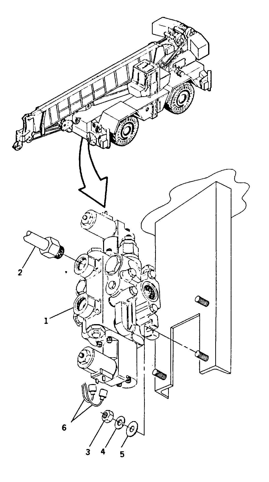
INTEGRATED OUTRIGGER CONTROL VALVE INSTALLATION
TOOLS: General mechanic’s tool kit: automotive (5180-00-177-7033)
SUPPLIES:
Loctite 545 (Item 13, Appendix C)
Hydraulic fluid (Item 6, Appendix C)
Preformed packings as required
Lockwashers (Item 57, Appendix C)
EQUIPMENT CONDITION:
Disconnect ground cable of shunt. (Refer to page 8-109.)
REMOVAL:
1.
REMOVE INTEGRATED OUTRIGGER CONTROL
VALVE (1).
a.
Tag and disconnect electrical leads (6) to
outrigger valve.
b.
Tag and disconnect six hydraulic lines (2) to
outrigger valve; cap all lines and openings.
c.
Remove three nuts (3), lockwashers (4) and
flatwashers (5) securing control valve (1),
remove valve. Discard lockwashers (4).
d.
Remove fittings and preformed packings from
valve as required. Save fittings for installation or
replace as necessary. Discard preformed
packings.
INSTALLATION:
1.
INSTALL INTEGRATED OUTRIGGER CONTROL
VALVE (1).
a.
Install fittings.
b.
Position valve (1) on mounting studs, secure
with washers (5), new lockwashers (4) and nuts
(3).
16-4


