TM 5-3810-306-20
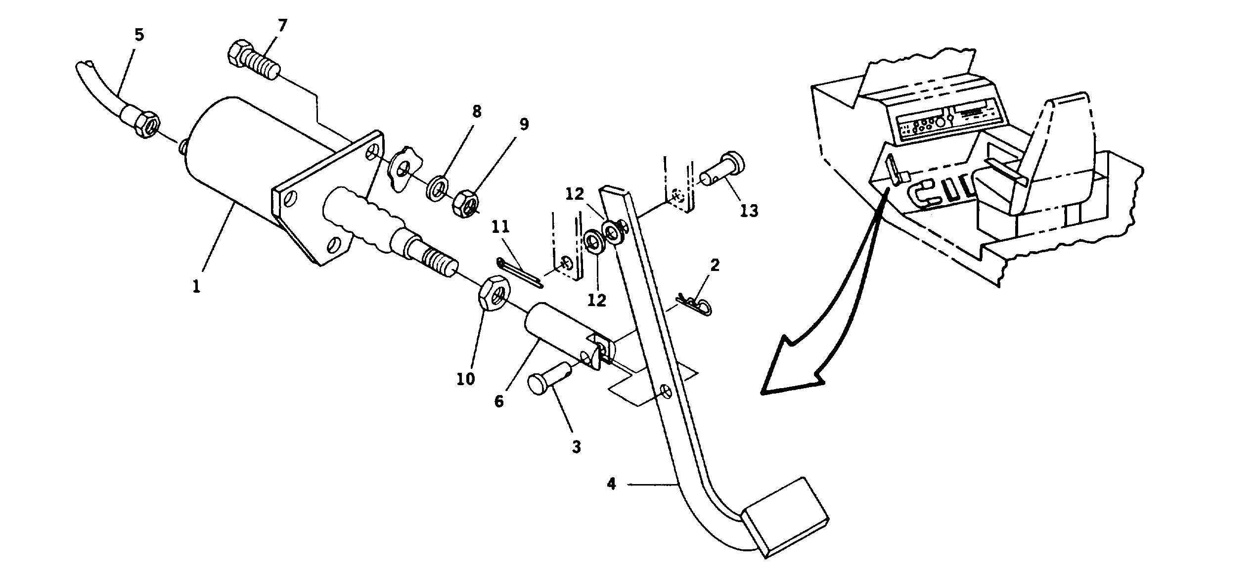
SWING BRAKE VALVE AND PEDAL INSTALLATION
TOOLS: General mechanic’s tool kit: automotive (5180-00-177-7033)
SUPPLIES:
Lockwashers (Item 15, Appendix C)
Cotter pin (Item 86, Appendix C)
EQUIPMENT CONDITIONS: Disconnect ground cable at shunt. (Refer to page 8-109.)
Cab front panel removed. (Refer to page 15-10.)
REMOVAL:
1.
REMOVE SWING BRAKE VALVE.
a.
Remove hitch pin (2) from clevis pin (3),
securing clevis (6) to brake pedal (4).
b.
Tag and disconnect three hydraulic hoses (5) to
brake valve (1). Remove fittings and retain for
reassembly.
c.
Remove three capscrews (7), lockwashers (8)
and nuts (9) securing swing brake valve (1) to
mounting plate. Remove valve (1) and discard
lockwashers (8).
2.
REMOVE PEDAL (4).
a.
Remove cotter pin (11), pin (13) and two
washers (12) securing pedal (4) to bracket.
Discard cotter pin (11).
b.
Remove pedal (4).
INSTALLATION:
1.
INSTALL PEDAL (4).
a.
Position pedal (4) in mounting bracket and
secure with pin (13), two washers (12) and new
cotter pin (11).
16-8


