I Replace all damaged or defective parts as
NOTE
necessary. Always replace connecting rod bearings as
Always coat both units of connecting rod bearing
matched sets.
shells with an approved lubricant before installing.
3-72. Reassembly and Installation
e Install lockplate and nuts on bolts and tighten
nuts as outlined below:
a Refer to figure 3-41 and assemble connecting
(1) Tighten both nuts to 55-60 ft-lbs.
rod and piston assemblies as shown.
(2) Tighten both nuts to 105-115 ft-lbs.
b Install connecting rod and piston assemblies
(3) Loosen both nuts completely to remove all
being sure to lubricate piston and rings with clean
tension.
lubricating oil, before installation.
(4) Tighten both nuts 30-32 ft-lbs.
c Install piston and rod assembly in cylinder
(5) Tighten both nuts to 60-65 ft-lbs.
positioned so numbered side of rod is toward outside of
(6) Advance the nuts 60 in 30 increments
block.
f Install next piston and rod assembly opposite the
one just installed. Secure rod to same crankshaft
CAUTION
journal. Install remaining assemblies in similar manner.
g Check tightened connecting rods to see that they
Pistons are marked to indicate which side is to be
are free to move sideways on crank journal. Check with
assembled to the "out" exhaust side.
hand pressure first; tap lightly with soft hammer only if
necessary.
d Install rod cap over blots so that numbered side
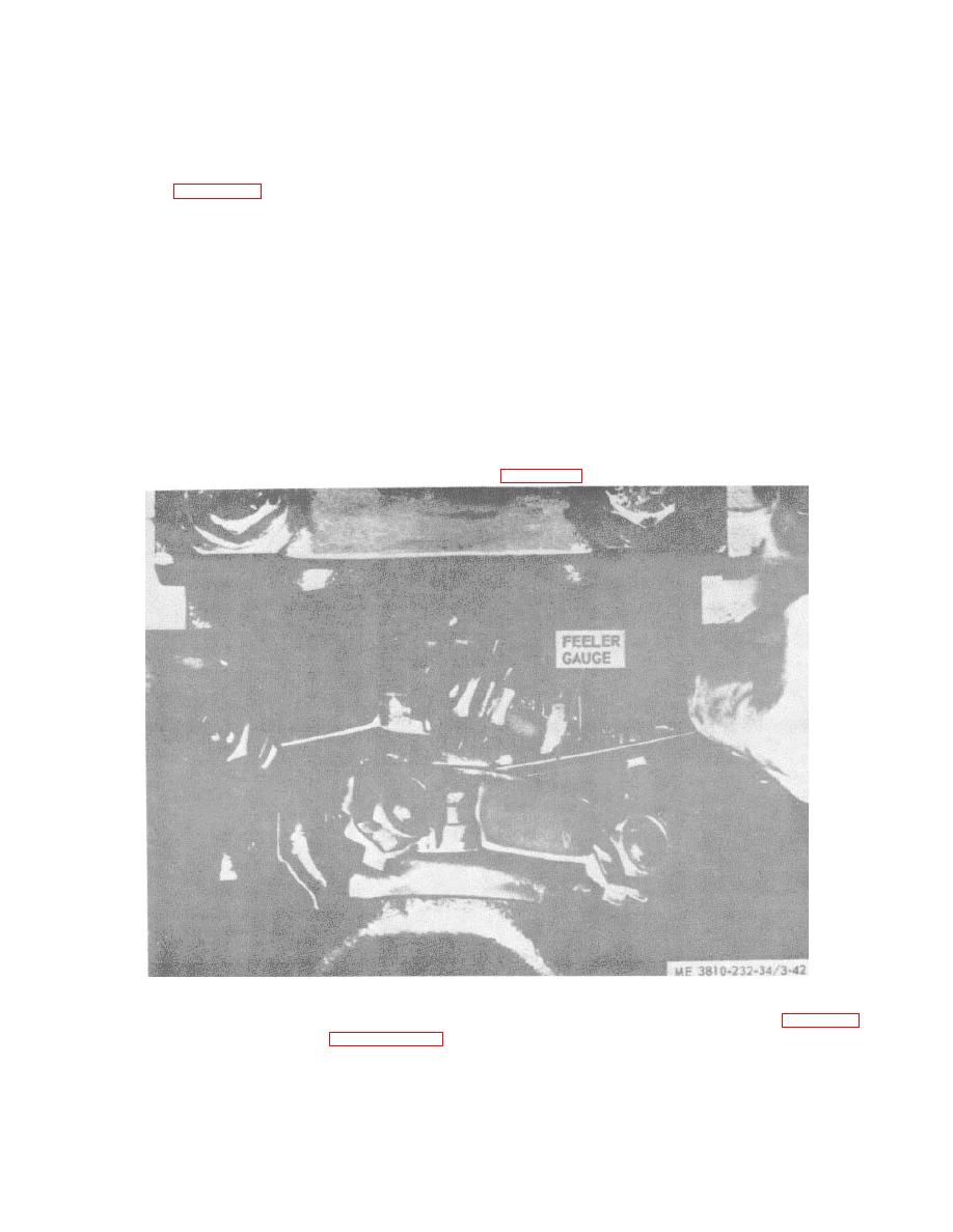
h Push rods apart; check for 0.008/0.016 inch
of cap is matched with numbered side of rod. Lubricate
clearance between rods with feeler gauge as shown in
bolt and nut threads.
Figure 3-42. Checking rod side clearance.
i Bend tangs on lock plates to secure nuts.
k Install cylinder head assemblies (para 3-49).
j Install
oil
pan
3-64


