TM5-3810-305-10
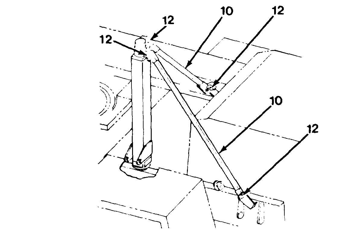
c. Remove two truss rods (10), adjustable
truss rod (11 ) and six pins (12) from
storage location A (Figure 5-11) on right
side of upperstructure. Install two truss
rods (1 O) to top of carrier frame, one on
left side, behind cab, and the remaining
one on right side of cab. Install four pins
(12) in connecting points (Figure 5-11A).
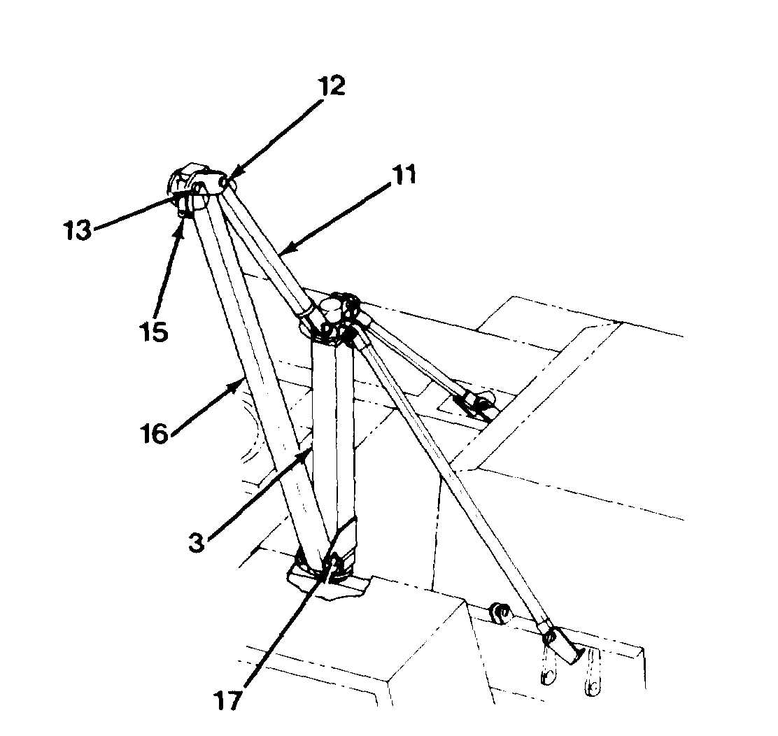
5. Install lift arm (16, Figure 5-12) as follows:
a. With lift arm (16) still in storage location
B on right side of boom, pull out sheave
pin (13) and remove sheave (14) from
sheave bracket (15, Figure 5-11 ).
b. Temporarily lay sheave (14) aside.
Weight of the lift arm is approxi-
mately 95 lb (43 kg). Use two
people to properly support and
lift the lift arm. Failure to follow
this procedure could cause
DEATH or serious injury.
Figure 5-11A. Installing the Truss Rods
c.
d.
e.
f.
Remove lift arm (16) and pins (17) and
(18) from storage brackets. Place pin (18)
in tool box for future use.
With sheave bracket (15) down, connect
lift arm (16) to base of mast (3) with pin
(17, Figure 5-12).
NOTE
Adjustable truss rod (11) has
been permanently adjusted for
the LRT 110 Crane and should
never require adjustment.
Using two pins (12), attach adjustable
truss rod (11) to top of lift arm (16) and
then to top of mast (3). Mast and arm as-
sembly is now complete.
Swing assembly around and position over
rear fender.
Figure 5-12. Assembling the Mast
5-31