
TM 5-3810-305-23
0078
REMOVAL
1.
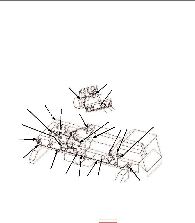
Disconnect main engine wiring harness (Figure 1, Item 12) from shunt (Figure 1, Item 21), hydraulic valve bank
(Figure 1, Item 6), winch valve (Figure 1, Item 10), fuel shutoff toggle switch (Figure 1, Item 8), front outrigger
solenoid valve (Figure 1, Item 9), collector ring (Figure 1, Item 5), fuel sender (Figure 1, Item 13), transmission
temperature sender (Figure 1, Item 4), axle centering light switch (Figure 1, Item 14), oil pressure sender
(Figure 1, Item 17), backup alarm (Figure 1, Item 19), rear outrigger solenoid valve (Figure 1, Item 3), water
temperature sender (Figure 1, Item 20), alternator (Figure 1, Item 2), starting motor solenoid and starting motor
relay (Figure 1, Item 1), speedometer sender (Figure 1, Item 7), taillights (Figure 1, Item 16), fuel solenoid
(Figure 1, Item 18), and turn signals (Figure 1, Item 15).
2.
Remove main engine wiring harness mounting clamps (Figure 1, Item 11), lockwashers and tiedown straps.
Discard tiedown straps and lockwashers.
3.
Remove main engine wiring harness (Figure 1, Item 12).
2
1
3
19
20
18
21
4
17
8
567
16
15
14
13
11
12
10
M0164105
9
Figure 1.
Main Engine Wiring Harness Removal.
END OF TASK
CLEANING
Clean parts IAW General Maintenance Instructions (WP 0162).
END OF TASK
03/15/2011Rel(1.8)root(maintwp)wpno(M00084)