
TM 5-3810-305-23
0160
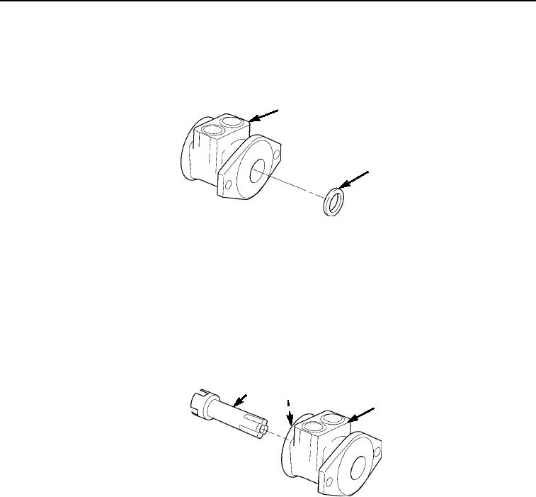
ASSEMBLY - Continued
5.
Apply molybdenum grease to seal lip and install dirt and new water seal (Figure 10, Item 2) in housing
(Figure 10, Item 1). Seat dirt and water seal against bearing, with seal lip facing bearing.
1
2
M0466105
Figure 10. Swing Motor Assembly.
6.
Place swing motor in a soft-jawed vise with mounting flange down, and clamp vise jaws against edges of
mounting flange.
7.
Install coupling shaft (Figure 11, Item 1) into housing (Figure 11, Item 3) seating it against thrust washer
(Figure 11, Item 2). Coupling shaft must rotate smoothly on thrust bearing package.
1
2
3
M0468105
Figure 11. Swing Motor Assembly.
03/15/2011Rel(1.8)root(maintwp)wpno(M00179)