
TM 5-3810-305-23
0163
ASSEMBLY - Continued
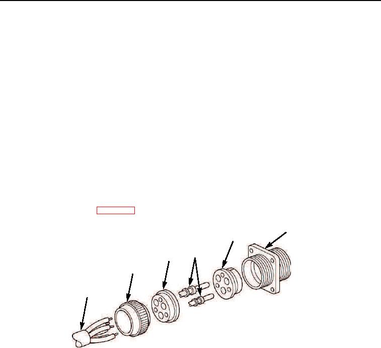
Male-Type Panel Mounting Receptacle with Ridged Locking Nut
1.
Strip cable insulation equal to depth of solder wells of pin contacts (Figure 15, Item 4).
2.
Slide nut (Figure 15, Item 2) over cable leads (Figure 15, Item 1).
3.
Slide grommet (Figure 15, Item 3) over cable leads (Figure 15, Item 1).
4.
Insert cable leads (Figure 15, Item 1) into solder wells of pin contacts (Figure 15, Item 4) and solder (use rosin
core solder only).
5.
Push insert (Figure 15, Item 5) into shell (Figure 15, Item 6) from rear until seated. Groove in insert must be
aligned with guide in shell to ensure proper fit.
6.
Push pin contacts (Figure 15, Item 4) into insert (Figure 15, Item 5) from rear until seated.
7.
Push grommet (Figure 15, Item 3) down cable leads (Figure 15, Item 1) and over solder wells of pin contacts
(Figure 15, Item 5)
8.
Screw nut (Figure 15, Item 2) onto shell assembly.
9.
Tape cable leads as required.
10.
Connect battery cables (WP 0076).
6
5
4
3
2
1
M0145105
Figure 15. Electrical Harness Assembly.
03/15/2011Rel(1.8)root(maintwp)wpno(M00186)