
TM 5-3810-305-23
0163
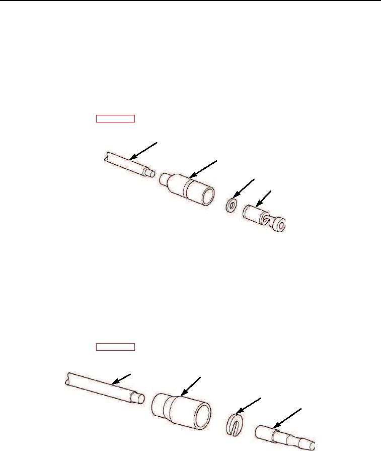
ASSEMBLY - Continued
Female Cable Connector with Washer
1.
Strip cable insulation approximately 0.125 inches (3.2 mm).
2.
Slide shell (Figure 10, Item 2) and washer (Figure 10, Item 3) over cable (Figure 10, Item 1).
3.
Place cable (Figure 10, Item 1) in cylinder end of terminal and crimp.
4.
Slide shell (Figure 10, Item 2) and washer (Figure 10, Item 3) over terminal (Figure 11, Item 4).
5.
Connect battery cables (WP 0076).
1
2
3
4
M0353105
Figure 10. Electrical Harness Assembly.
Male Cable Connector with Washer
1.
Strip cable insulation equal to depth of ferrule well.
2.
Slide shell (Figure 11, Item 2) over cable (Figure 11, Item 1).
3.
Insert cable (Figure 11, Item 1) into terminal (Figure 11, Item 4) well and crimp.
4.
Place C-washer (Figure 11, Item 3) over cable (Figure 11, Item 1) at crimped junction and slide shell
(Figure 11, Item 2) over C-washer and terminal (Figure 11, Item 4).
5.
Connect battery cables (WP 0076).
1
2
3
4
M0141105
Figure 11. Electrical Harness Assembly.
03/15/2011Rel(1.8)root(maintwp)wpno(M00186)